- 您现在的位置:买卖IC网 > Sheet目录367 > UBA2032TS/N2,118 (NXP Semiconductors)IC DRIVER FULL BRIDGE 28-SSOP
�� �
�
Philips� Semiconductors�
�Full� bridge� driver� IC�
�The� oscillation� can� take� place� in� three� different� modes:�
�?� Internal� oscillator� mode.�
�Product� speci?cation�
�UBA2032�
�handbook,� halfpage� GHR�
�In� this� mode� the� bridge� commutating� frequency� is�
�determined� by� the� values� of� an� external� resistor� (R� osc� )�
�and� capacitor� (C� osc� ).� In� this� mode� pin� EXTDR� must� be�
�connected� to� pin� +LVS.� To� realize� an� accurate� 50%� duty�
�factor,� the� internal� divider� should� be� used.� The� internal�
�divider� is� enabled� by� connecting� pin� DD� to� pin� SGND.�
�Due� to� the� presence� of� the� divider� the� bridge� frequency�
�is� half� the� oscillator� frequency.� The� commutation� of� the�
�bridge� will� take� place� at� the� falling� edge� of� the� signal� on�
�pin� RC.� To� minimize� the� current� consumption�
�pins� +LVS,� ?� LVS� and� EXTDR� can� be� connected�
�together� to� either� pin� SGND� or� pin� V� DD� .� In� this� way� the�
�current� source� in� the� logic� voltage� supply� circuit� is� shut�
�off.�
�?� External� oscillator� mode� without� the� internal� divider.�
�In� the� external� oscillator� mode� the� external� source� is�
�V�
�VSHR�
�VGHL�
�VSHL�
�Vhalf� bridge� left�
�Vhalf� bridge� right�
�0�
�0�
�0�
�0�
�t� (sec)�
�MGU545�
�connected� to� pin� EXTDR� and� pin� RC� is� short-circuited� to�
�pin� SGND� to� disable� the� internal� oscillator.� If� the� internal�
�divider� is� disabled� (pin� DD� connected� to� pin� V� DD� )� the�
�duty� factor� of� the� bridge� output� signal� is� determined� by�
�the� external� oscillator� signal� and� the� bridge� frequency�
�Fig.4�
�Half� bridge� and� higher/lower� side� driver�
�output� signals.�
�(� k� osc� � R� osc� � C� osc� )�
�equals� the� external� oscillator� frequency.�
�?� External� oscillator� mode� with� the� internal� divider.�
�The� external� oscillator� mode� can� also� be� used� with� the�
�internal� divider� function� enabled� (pin� RC� and� pin� DD�
�connected� to� pin� SGND).� Due� to� the� presence� of� the�
�divider� the� bridge� frequency� is� half� the� external� oscillator�
�frequency.� The� commutation� of� the� bridge� is� triggered�
�by� the� falling� edge� of� the� EXTDR� signal� with� respect� to�
�V� ?� LVS� .�
�If� the� supply� voltage� on� pin� V� DD� or� pin� HV� drops� below� the�
�reset� level� of� power� drive,� the� UBA2032� re-enters� the�
�start-up� phase.� The� design� equation� for� the� bridge�
�1�
�oscillator� frequency� is:� f� bridge� =� --------------------------------------------------� .�
�Non-overlap� time�
�Divider� function�
�If� pin� DD� is� connected� to� pin� SGND,� then� the� divider�
�function� is� enabled/present.� If� the� divider� function� is�
�present,� there� is� no� direct� relation� between� the� position� of�
�the� bridge� output� and� the� status� of� pin� EXTDR.�
�Start-up� delay�
�Normally,� the� circuit� starts� oscillating� as� soon� as� pin� V� DD� or�
�pin� HV� reaches� the� level� of� release� power� drive.� At� this�
�moment� the� gate� drive� voltage� is� equal� to� the� voltage� on�
�pin� V� DD� for� the� low� side� transistors� and� V� DD� ?� 0.6� V� for� the�
�high� side� transistors.� If� this� voltage� is� too� low� for� sufficient�
�drive� of� the� MOSFETs� the� release� of� the� power� drive� can�
�be� delayed� via� pin� SU.� A� simple� RC� filter� (R� between�
�pin� V� DD� and� pin� SU;� C� between� pin� SU� and� pin� SGND)�
�can� be� used� to� make� a� delay,� or� a� control� signal� from� a�
�processor� can� be� used.�
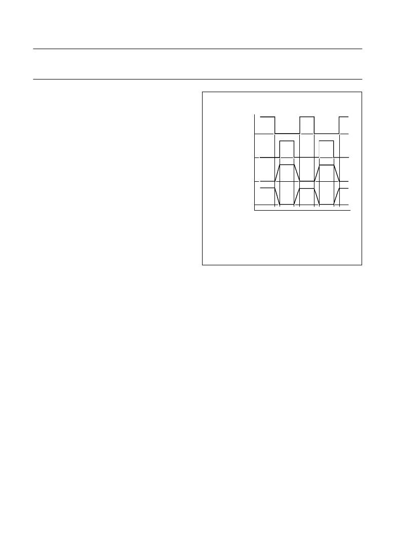
�The� non-overlap� time� is� the� time� between� turning� off� the�
�conducting� pair� of� MOSFETs� and� turning� on� the� next� pair.�
�The� non-overlap� time� is� realized� by� means� of� an� adaptive�
�non-overlap� circuit.� With� an� adaptive� non-overlap,� the�
�application� determines� the� duration� of� the� non-overlap� and�
�makes� the� non-overlap� time� optimal� for� each� frequency.�
�The� non-overlap� time� is� determined� by� the� duration� of� the�
�falling� slope� of� the� relevant� half� bridge� voltage� (see� Fig.4).�
�The� occurrence� of� a� slope� is� sensed� internally.� The�
�minimum� non-overlap� time� is� internally� fixed.�
�2005� Mar� 24�
�6�
�Bridge� disable�
�The� bridge� disable� function� can� be� used� to� switch� off� all� the�
�MOSFETs� as� soon� as� the� voltage� on� pin� BD� exceeds� the�
�bridge� disable� voltage� (1.29� V).� The� bridge� disable�
�function� overrules� all� the� other� states.�
�发布紧急采购,3分钟左右您将得到回复。
相关PDF资料
UBA2033TS/N2,118
IC FULL BRIDGE DRIVER 28-SSOP
UBA3070T/N1,118
IC LED DVR WHITE BCKLGT 8-SOIC
UEVM4430G-01-00-00
PANDABOARD
UEVM4460G-02-01-00
PANDABOARD ES
UHDM7218BPA
PLATE BARRIER 71.86X17.87" GRY
UHDM7218ECA
PLATE END 71.86X17.87" GREY
UHDM7218EPA
PLATE END 71.86X17.87" GREY
UHDM8418BPA
PLATE BARRIER 83.9X17.9X0.1" GRY
相关代理商/技术参数
UBA2032TS/N2/N,118
功能描述:功率驱动器IC Full Bridg Driver IC RoHS:否 制造商:Micrel 产品:MOSFET Gate Drivers 类型:Low Cost High or Low Side MOSFET Driver 上升时间: 下降时间: 电源电压-最大:30 V 电源电压-最小:2.75 V 电源电流: 最大功率耗散: 最大工作温度:+ 85 C 安装风格:SMD/SMT 封装 / 箱体:SOIC-8 封装:Tube
UBA2032TS/N3,118
功能描述:功率驱动器IC LIGHTING HID DRIVER RoHS:否 制造商:Micrel 产品:MOSFET Gate Drivers 类型:Low Cost High or Low Side MOSFET Driver 上升时间: 下降时间: 电源电压-最大:30 V 电源电压-最小:2.75 V 电源电流: 最大功率耗散: 最大工作温度:+ 85 C 安装风格:SMD/SMT 封装 / 箱体:SOIC-8 封装:Tube
UBA2032TS/N3,518
功能描述:功率驱动器IC UBA2032TS/SSOP28/REEL13DP//N3 RoHS:否 制造商:Micrel 产品:MOSFET Gate Drivers 类型:Low Cost High or Low Side MOSFET Driver 上升时间: 下降时间: 电源电压-最大:30 V 电源电压-最小:2.75 V 电源电流: 最大功率耗散: 最大工作温度:+ 85 C 安装风格:SMD/SMT 封装 / 箱体:SOIC-8 封装:Tube
UBA2032TS/N3-T
功能描述:功率驱动器IC LIGHTING HID DRIVER RoHS:否 制造商:Micrel 产品:MOSFET Gate Drivers 类型:Low Cost High or Low Side MOSFET Driver 上升时间: 下降时间: 电源电压-最大:30 V 电源电压-最小:2.75 V 电源电流: 最大功率耗散: 最大工作温度:+ 85 C 安装风格:SMD/SMT 封装 / 箱体:SOIC-8 封装:Tube
UBA2033
制造商:PHILIPS 制造商全称:NXP Semiconductors 功能描述:HF full bridge driver IC
UBA2033TS
制造商:PHILIPS 制造商全称:NXP Semiconductors 功能描述:HF full bridge driver IC
UBA2033TS/N2,118
功能描述:功率驱动器IC LIGHTING HID DRIVER RoHS:否 制造商:Micrel 产品:MOSFET Gate Drivers 类型:Low Cost High or Low Side MOSFET Driver 上升时间: 下降时间: 电源电压-最大:30 V 电源电压-最小:2.75 V 电源电流: 最大功率耗散: 最大工作温度:+ 85 C 安装风格:SMD/SMT 封装 / 箱体:SOIC-8 封装:Tube
UBA2033TS/N2-T
功能描述:功率驱动器IC LIGHTING HID DRIVER RoHS:否 制造商:Micrel 产品:MOSFET Gate Drivers 类型:Low Cost High or Low Side MOSFET Driver 上升时间: 下降时间: 电源电压-最大:30 V 电源电压-最小:2.75 V 电源电流: 最大功率耗散: 最大工作温度:+ 85 C 安装风格:SMD/SMT 封装 / 箱体:SOIC-8 封装:Tube